Today Let’s study one Inverter 500w device. it is for dc 12v to ac 220voltage.
Box of Inverter 500w
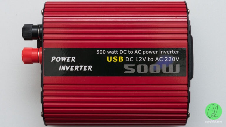
The unit itself is in a red, rounded metal shell which is quite attractive compared to the boxy shape of regular units. It has a label on the top which has no mention of pure-sine-wave (which was in the listing I purchased the unit from). There is also no branding, although the USB aspect is listed.
Rear of Inverter 500w
There seem to be some visually-similar units avai
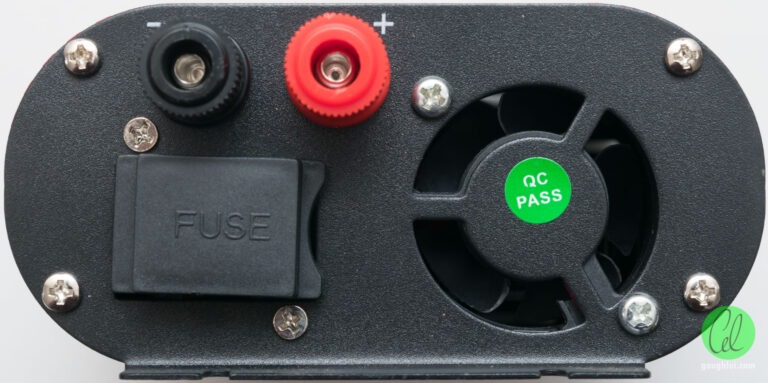
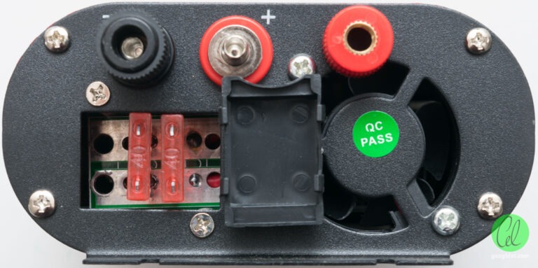
The butt end of the unit has two combination banana socket and binding post terminals, a fuse block which is covered by a cap and a 40mm fan for cooling.
Front of Inverter 500w
The feel of these terminal posts is pretty flimsy and lightweight – the depth of the socket is not sufficient to fully engage a banana plug either. Surprisingly, the fuse area contains two 40A fuses in parallel rather than protecting each polarity. That means that somehow, the designer thinks that 80A (corresponding to 960W) could conceivably safely run through the inverter which I really doubt given how flimsy the terminals are. Perhaps it was desperation to reduce voltage loss over the fuses, but in return, that probably compromises the protective benefit they may have against fire due to faults. This poses another danger, as inevitably, many of these products use a crowbar diode for reverse polarity protection – you’d have to pass well over 80A to blow the two fuses in a timely manner!
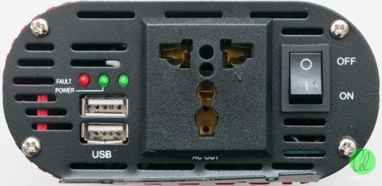
The front end of the unit is a little different from all the other units I’ve seen online. It has a universal socket in the centre, the power toggle to the right, but the LED indicators and dual USB output to the left. Most of the other units I’ve seen have the universal socket on the right and everything else to the left – perhaps this is a new version or a copy of the other units? It is also noted that the mounting “ear” on the frame is bent upward – this doesn’t appear to be shipping damage, but is perhaps bad handling during manufacture.
Accessories of Inverter 500w
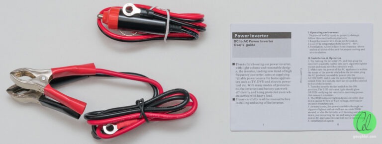
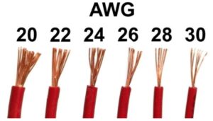
The unit came with some cables, as they ordinarily do. The cigarette lighter cable was made of 1mm^2 cable but without a fuse in the plug, while the clip leads had 12AWG. The cigarette lighter cable was probably a bit thin for my liking, ultimately relying on the vehicle’s fuse to prevent overloading. Similarly, the clip cable is also a little thin considering the two 40A fuses in the inverter and the power rating. Even the ring crimps felt rather flimsy and lightweight – I had very little confidence they would handle 500W + losses due to efficiency at 12V which would need about 46A (or a recommended ~6mm^2 cable). It’s all due to cost reduction, I suppose. It did come with a small generic stapled bilingual manual which could have applied to any inverter and didn’t state anything apart from the obvious. This gave me the feeling that perhaps this would soon become an AU$42 regret.
Couldn’t Smell the Trouble Brewing
The first thing I did was to hook it up to my bench power supply and give it a whirl. Setting the input to 12V, 2A current limited, I expected the unit to come up with a quiescent current draw in the ~0.3-0.5A region, mainly due to the fan.
The rightmost green light illuminated to indicate 12V was applied. The fault LED briefly lit and then went out. Then what happened was a little surprising – the bench supply was current limiting! I left it in this state for a few seconds before turning it off and just double checking everything – nope, the output was unplugged and there was nothing on the USB.
I surmised that perhaps the USB circuitry wasn’t so efficient or there may be some other strange reason this inverter needs more current to start up, so I upped the limiter to 5A. Again, it current limited and after five seconds, I shut it off. That was 60W going into the box with nothing else plugged in.
At this point, I was a little circumspect but I noted that the unit had two 40A fuses which were intact, so perhaps it just needs more. I decided to up it to 10A and that would be my absolute limit to get it to come up. I turned it on, it current limited again but after two seconds, it fell down to a comfortable 3-4W idle power.
But that would be the closest it ever got to powering up – the green power LED never lit and the output measured exactly zero volts. Shutting it off and powering it back up, it went straight for the 3-4W consumption which I suspect was mostly from the fan which seemed to be the only thing working hard. The unit was dead on arrival.
I suspected something internal probably burned out or shorted out due to poor construction, but there was no smell. Nothing rattling, no smoke, no pops and absolutely nothing untoward.
PCBA of Inverter 500w
Disappointed having wasted the better part of over a month waiting for this, I contacted the seller and after a few back-and-forth exchanges and a wait of two days, a full refund was provided and the unit remained in my possession. This means it’s time to do some science.
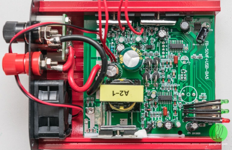
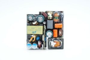
Removing the lid off this unit was not difficult – just remove the four screws at the plug end to allow that end of the unit to come off, then remove the two upper screws at the far end to allow the top shell to slide off, revealing the internals.
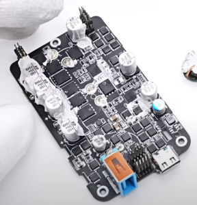
It is a rather compact package inside – it’s clear to see that the two 40A fuses are indeed in parallel. It’s also clear to see that it seems extremely cost-reduced – the buzzer isn’t even fitted to this unit (which is a bonus, I suppose) and the LEDs don’t even have a proper mounting, just being “held up” by their legs inside heatshrink tubing. Worst of all is that the output socket actually collides with the PCB on the bottom edge, distorting its fit on the end panel.
FAN of Inverter 500w
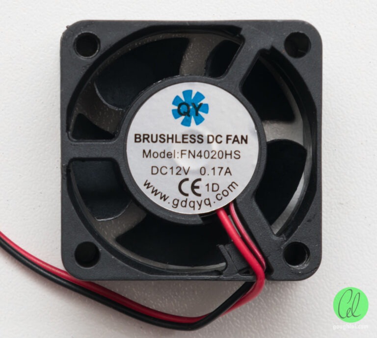
I needed to take it further apart, so I started removing items that would easily come off. This included the 40mm fan which comes from a relatively unknown QY (www.gdqyq.com) FN4020HS “high speed” fan rated at 12V 170mA (or 2.04W). Only two screws hold this into the backplate – yet another sign of cost-reduction.
MOSFET of Inverter 500w
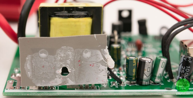
Removing the screws from the sides that hold the pressure-bars against the TO-220 MOSFET packages, the PCB can then slide out of the casing. This reveals the bottom pair of transistors (Q1, Q2) being insulated from the case with a silicone sheet that has some white thermal paste (and white silicone holding a thermistor for overheat protection monitoring). That’s not too bad in itself, but just look at the random sized and branded capacitors … no quality there!
The other side shows only three of the four transistors have thermal paste actually visible on the die-part of the package, indicating poor manufacturing practice.
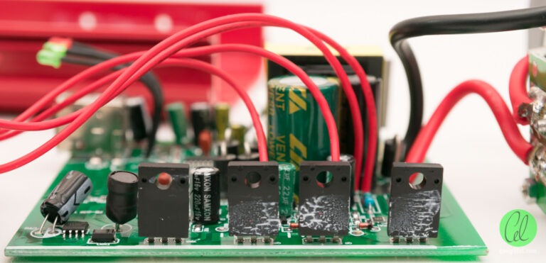
The insulated-tab transistors on the top are definitely responsible for chopping up the output – these seem to be Toshiba K8A50D 500V/8A/0.7R N-channel MOSFETs
This leaves the bottom pair as the transistors responsible for converting the input DC into an AC waveform with the centre-tapped transformer primary winding. These appear to be FeiHong FHP100N07 68V/100A/6.5mR N-channel MOSFETs.
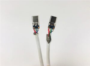
The soldering on most of the board looks okay, although the soldering on one of these two MOSFETs did look a bit poor. The really brown connection might look bad but is still probably functional, as that is the gate drive pin which passes barely any current at all.
Logic circuit of Inverter 500w
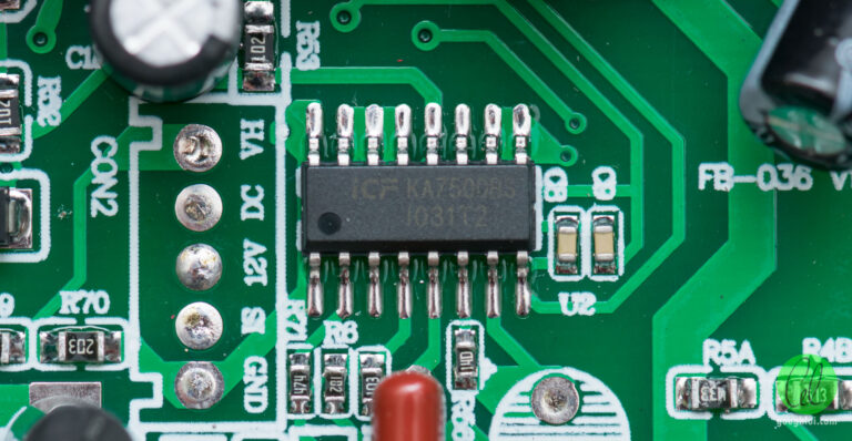
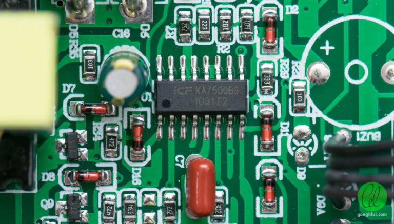
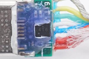
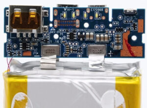
The logic in the unit resides in two ICF KA7500BS integrated circuits, which appear to be a clone of the Fairchild KA7500B SMPS Controller chips. At a guess, the lower chip is probably responsible for chopping up the DC into the transformer to turn it into high voltage AC which is rectified by the bridge rectifier that is formed by the four discrete diodes into the large capacitor. The upper chip would probably then chop that DC into a square wave AC using the four Toshiba insulated-tab MOSFETs to produce the output. Of note that based on the parts seen, there is no way this unit could be true-sine-wave – the seller was pretty much lying on that point.
Also of note is that the USB output seems to be a bit of an afterthought, tacked onto the board as a separate SMPS occupying the top right corner of the board.
Related Products:
BPG12-100(12V100Ah) deep cycle gel battery
12V150Ah deep cycle gel battery
12V200Ah deep cycle gel battery
Related Products Application:
Start-Stop AGM Battery Applications
7 Applications of Long Life AGM Battery
gel battery application
Related Posts:
Tags: Lithium battery. LiFePO4 battery.