TOSHIBA Laptop-Lithium Battery
TOSHIBA Laptop Battery and BMS Overview
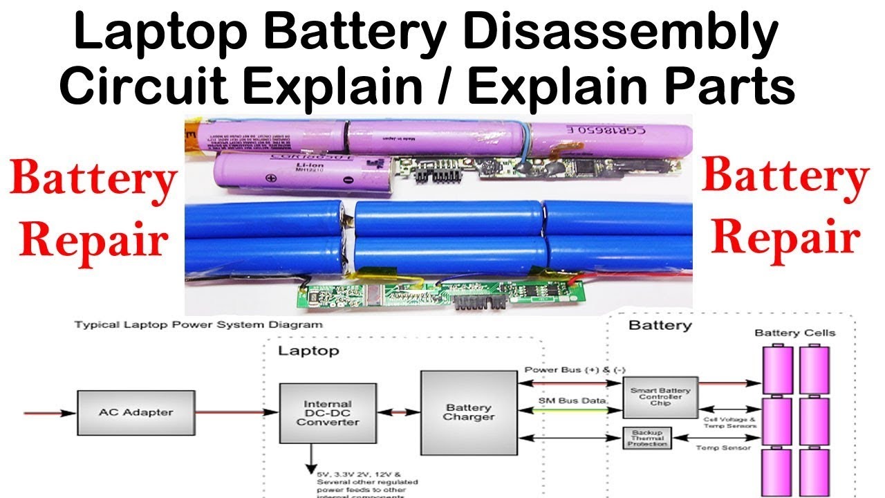
Before anything else we must acknowledge that today’s laptop battery is not an ordinary battery pack with a bunch of rechargeable cells inside. It is in fact a smart battery pack.
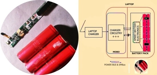
This is the typical laptop battery system diagram. The smart controller electronics that reside inside the battery pack makes it smart, and it is the heart of the smart battery system. The clever electronics play multiple roles in the game, like storing the battery parameters, monitoring the charge and discharge processes in real time to provide feedback to the charger electronics, maintaining a statistical calculation of the battery health level, etc. Moreover, a laptop battery packed with lithium-ion battery cells typically holds three different thermal safety mechanisms. The primary temperature monitor, working together with a smart chip, communicates to the charger circuitry over the system management bus (SMB). If for some reason the smart chip fails or the charger circuitry fails to handle the smart chip data, the secondary monitor takes its role. If both of these fail, then a thermal cut-off circuitry located inside of the battery itself take control to disconnect the battery cells.
Now it’s worth noting that, usually the protection electronics inside the laptop battery pack is used for preventing the battery cells being exposed to malpractices, and also to monitor battery capacity for the battery fuel-gauge. It’s not employed for actually charging the battery – there will be a dedicated charger circuitry within the laptop motherboard itself to do that.
Admittedly I only just scratched the surface of laptop batteries! Look, laptop battery electronics has witnessed a very steep progress curve in just a couple of years. Today, even a cheap laptop battery pack has many complex chips for the sole purpose of handling the delicate battery cells. Market giants Texas Instruments and Maxim produce Smart Battery compliant chips of which many found their chair in most laptop battery packs (and in laptops).
SMBus (https://en.wikipedia.org/wiki/System_Management_Bus) Quick Start Guide: https://www.nxp.com/docs/en/application-note/AN4471.pdf
Smart Battery System (https://en.wikipedia.org/wiki/Smart_Battery_System) Specifications: http://smartbattery.org/specs/sbdat110.pdf
Engineer’s Surgery
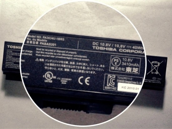
The original battery pack of my spare laptop (Toshiba) became old in the past 6 years, and I quickly jumped into getting a new one to replace it. It made a deep hole in my pocket but I am not too upset about it because I was thrilled by the thought that I simply got an new toy to take apart (hope my wife never find this post)!
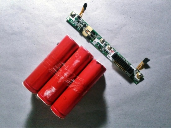
That same night I started the teardown, and after quickly taking apart the casing I was presented with half-dozen Lithium battery cells and a large ribbon of electronics. My careless fiddling left a wake of totally damaged battery casing!
TOSHIBA Laptop-Lithium Battery BQ8030DBT
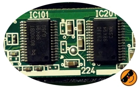
As touched on before, this one is also a smart battery (SB) and it has an I2C-like communication protocol – the System Management Bus (SMB) or BMS (Battery Management System), conforms to the Smart Battery Specifications. Below you can see some of the chips in my laptop battery PCB.
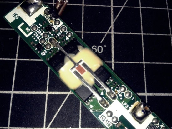
Now I will briefly describe how these pieces make the laptop battery smart (of course, there are a few more tiny chips scattered about, with vague markings).
- bq8030DBT (*)
- bq29330 (https://www.ti.com/lit/ds/symlink/bq29330.pdf)
- TPC8028 (http://pdf.tixer.ru/525793.pdf)
- CEFJ91 (*)
The bq29330 is a 2-series, 3-series, and 4-series cell lithium-ion battery pack full-protection analogue front end (AFE) IC. And the TPC8028 is a Toshiba Field Effect Transistor (Silicon N Channel MOS Type). A total of 4 of them are used here in the charge/discharge control circuit.
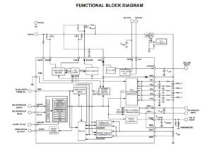
I tried to get the datasheets of BQ8030DBT and CEFJ91, however, I cannot find both on the web. Finally, I was informed by a TI forum member that bq80xx family of chips are not sold to the mass market so there is no public information available. And, there’s no easy way to find CEFJ91. Well that’s not good. I hope someone can help me out.
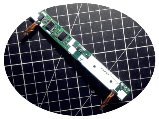
Anyway, I’m sure that bq8030DBT is the real brain here, and it’s an SBS-compliant gas gauge IC. So, this chip can directly interact with the host thru smart battery specification (SBS) data over system management bus (SMB). Presumably, it has a reprogrammable flash data as well as portions of the firmware itself can be altered. In other words, this chip is actually a microprocessor running on-chip embedded firmware. It communicates with the laptop electronics through the SMB (the battery gauge chip has a bunch of memory registers which can be read and set through the system management bus).
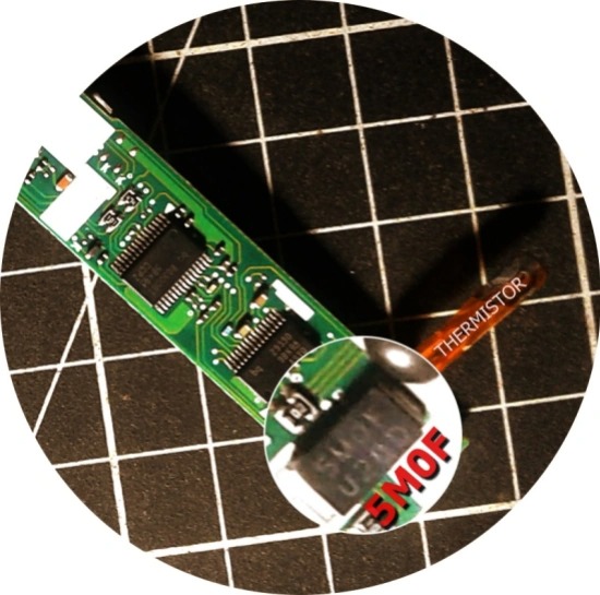
Now to the “fuse” components. I can see two fuses (and a pair of thermistors for monitoring battery temperature) in my circuit board. The first fuse is a big 2-pin chip with the mark 5M0F.
This is the second fuse (believe me)!
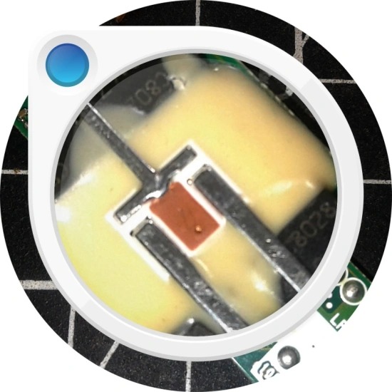
Most datasheets call this weird 3-legged (sometimes 4-legged) fuse as “fuse-resistance protector” or “miniature battery logic fuse”. I suppose the intention is to provide a way for the microcontroller to physically break the circuit if it detects a potentially hazardous situation like overheating of the mosfet circuitry (abnormal charge/discharge conditions). To check this fuse, you can do a continuity test on longer sides, and for the heater resistance (10-22Ω typical) measure the resistance between either fuse contact and the heater pin (see below). This is a randomly picked datasheet –

Coming to the pinout of my laptop battery connector, the lithium-ion cells are arranged in ‘3 series 2 parallel’ configuration (3S2P), and the blades at both ends of the 9-blade/pin battery connector are ‘power’ terminals (Pin 9 and 8: Negative/Pins 2 and 1: Positive). The SMB is on pins 6 and 7. Pin 4 is the “system presence/sense” pin, and Pin 5 is the “thermistor” pin. Pin 3 not yet identified; May be a STAT/INT/ID/NC (reserved) pin. Who knows?
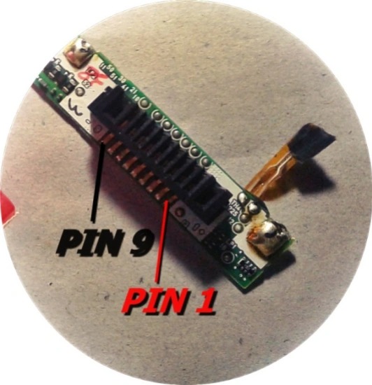
At this point, it’s good to take note of the fact that a typical smart battery has six or more battery connection terminals consisting of positive and negative battery terminals, thermistor, clock and data. Although the connections are often unmarked, the positive and negative are commonly located at the outer edges of the battery connector and the inner contacts accommodate the clock and data. For safety reasons, a separate thermistor wire is directly brought to the outside. Besides, some batteries are equipped with a solid-state switch that is normally in the off position and no voltage available at the battery terminals. Connecting the switch terminal to ground probably turns the battery on. Sometimes, this battery-wakeup pin is denoted as “system present/sense” pin.
bq8030DBT Update!
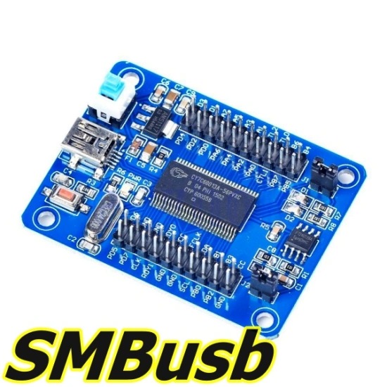
After scratching my head over a few weeks, at last I found that bq8030DBT is the blank version of bq20z90, and we can buy it from AliExpress (still there’s no public datasheet). Since the blank version usually comes up with the TI Boot ROM, it’s hoped that there’ll be a way to upload firmware and data flash (E2PROM), perhaps thru the flash tool included in SMBusb tool. More on this later.
- bq20z90 Technical Reference https://www.ti.com/lit/er/sluu264a/sluu264a.pdf
- SMBusb https://github.com/karosium/smbusb
Hacking and the Pocket Challenge
At this point we know what’s lodged in a typical smart laptop battery. However, we don’t have any insight into how to communicate with it. It can be done, but some experience with electronics and ‘low-level’ reverse engineering is mandatory.
If you’re going to attempt some laptop battery hacks, you should note that you have to gather a couple of ‘tools’ to proceed farther. Also be prepared to face the reality that often things could go horribly wrong if you don’t know what you’re doing. Further, there’s no guaranteed way to recover the investment in pricey tools and accessories unless you own a far-famed laptop repair firm. This is not to discourage you; look below to get a rough idea on setting your battery hack workbench up with good old and new tools (Google is your best friend).
- SMBusb Adapter
- CP2112 Adapter
- CH341T Adapter
- EV2300 EVM Interface Board
- EV2400 EVM Interface Board
- Arduino, Rpi, UBIA (USB/BLE to I2C/ADC Adapter – https://github.com/pvvx/UBIA)
After recognizing the SMBus lines, you can of course ‘listen’ to the communication between a smart laptop battery and motherboard electronics. Only three wires are necessary here: Data (SDA), Clock (SCK) and Ground (GND). No external pullup resistors are needed because most I2C/SMBus adapters have them onboard. You can even try Saleae logic analyser to see the communication as it has an I2C data processor. Another quick (much better, indeed) pick is the Beagle I2C protocol analyser. Trust me, Arduino (or Rpi) can be employed here as well!
The ultimate goal of a laptop smart battery hack, however, would be to rewrite capacity and cycle values to cheat the battery’s brain chip to think it’s in a brand-new battery. This often demands higher-level expertise, and great skill in reverse engineering binary data files, etc.
Even so, I decided to take various laptop smart battery packs just to see if I can hack them or not. I had already bought a few cheap tools from webstores, and certain costly jigs are on the way. Sometime later I’ll have to delve further into the laptop battery firmware hack. We’ll just have to see 😊

